
Industrial robots are good at repeating taught motions, but disassembly targets do not always remain exactly where a fixed program expects them. This paper combines the Interfacing Toolbox for Robotic Arms (ITRA) with decoupled hybrid visual servoing (DHVS), allowing camera observations to update robot motion during battery-handling subtasks.
The Integration Problem
A vision algorithm and a robot controller operate on different kinds of information and different clocks. The camera delivers observations, perception estimates a target, and the controller must turn that estimate into motion while meeting its own timing requirements. Simply sending occasional target positions does not provide continuous tracking.
ITRA connects an external computer to KUKA’s Robot Sensor Interface (RSI). The paper distinguishes controller-level KRL trajectory handling, externally generated trajectories, and RSI-based online trajectory generation. The distinction matters when a target moves: a controller that finishes a previously supplied motion before accepting another target cannot react in the same way as one that updates the trajectory online.
How Visual Feedback Becomes Motion

Image-based visual servoing reduces the difference between observed image features and their desired image locations. Position-based servoing instead reasons about a reconstructed spatial pose. DHVS combines these ideas while separating lateral camera motion from depth and rotational motion. Its interaction matrices relate movement of the camera to changes in observed features, allowing the controller to calculate corrective velocities.
This is a feedback process, not one-time detection followed by an entirely open-loop move. A new observation changes the error; the controller updates motion; the camera observes the result. Calibration links the image and robot coordinate systems, while gain selection affects the balance between quick convergence and oscillation.
The robot communication loop and camera stream remain distinct. A 250 Hz exchange has a 4 ms period, whereas a 60 Hz camera supplies a new frame roughly every 16.67 ms. Frequent communication helps deliver commands promptly, but cannot create new visual information between camera frames.
What Was Demonstrated
The experiments use KUKA KR10 and KR500 platforms for different purposes. KR10 trials demonstrate rapid marker tracking, bolt tracking and module tracking. KR500 demonstrations examine locating and sorting the top case and battery modules, connecting the tracking capability to heavier handling operations.
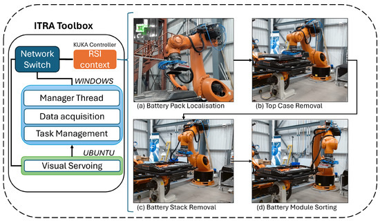
The reported mean durations distinguish localisation from handling: 27 seconds for top-case localisation and 39 seconds for removal; 32 seconds for stack localisation and 24 seconds for module sorting. These are measurements of particular subtasks. Adding them does not establish a separately measured complete-pack cycle time, because preparation, detachment and other operations are outside those timing boundaries.
What the Results Establish
The contribution is an integrated route from perception to adaptable industrial-arm motion. It shows how a common communication layer can support different tracking and handling demonstrations, while keeping perception and control responsibilities identifiable. It does not show that one software interface makes arbitrary new hardware automatically compatible.
The study also makes the limits of the disassembly claim important. Experiments ran in T1 manual reduced-velocity mode, and connectors, cables and other components had already been removed for the handling demonstrations. Success therefore concerns locating and moving prepared components, not unsupervised dismantling of an intact pack at production speed.
Remaining Engineering Questions
Calibration error, stale observations, occlusion and controller tuning all influence tracking. Force-sensor integration is identified as future work, so visual alignment should not be described as demonstrated force-controlled detachment. Physical replication requires the matching robot programs, tool geometry, camera calibration and experimental protocol, not only the published timing figures.
The broader significance is architectural: a useful robotic capability emerges from coordinating sensing, communication and trajectory generation. Each layer still needs its own validation, especially when moving from a research test bed to a different industrial process.
Testing and Real-World Use
The feedback loop could be tested with recorded or simulated moving targets by measuring tracking error together with observation age and command timing. It could support adaptable component localisation and handling where fixed taught positions are insufficient, subject to task-specific hardware and safety validation.