Structured Programming with Microcontrollers Class project
Instructions
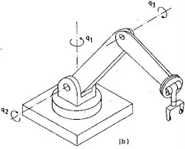
- The stepper motor (M1) of the base, which performs the rotation indicated by q1, must be able to move 360 ° to make complete revolutions through its axis.
- The stepper motor (M2) that performs the rotation in q2, must be able to move through a 180 ° arc that begins on the positive side of the X axis, this because it has physical limitations due to its position.
- The stepper motor (M3) that performs the q3 turn, should only be able to get in line with the previous link and make a downward turn with a maximum angle of 150 °.
- M2 and M3 motors must have sensors that indicate the start and end of the stroke to avoid damage to the equipment. If the system detects that one of the limit sensors has been activated, then it must stop and warn that it has reached the end through one of 4 LEDs.
- The system must include a method to select from the computer screen and through serial communication, which motor we want to move.
- Once the motor is selected, it must be moved back and forth through 2 computer keys (F and B) in pulse-to-pulse format (Jogging), also through serial communication.
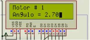
- The data of which motor is moving (Motor #) and the angle value (Angle =) should be displayed on the LCD screen connected to the AVR microcontroller.
- Once this system allows the proper movement of the 3 motors, the motors will be moved to a specific point.
- When the system reaches the desired position for each of the 3 links, it should be permanently stored in the microcontroller memory, the AVR’s EEPROM memory.
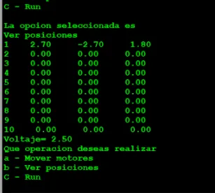
- A total of 10 positions must be stored.
- The program must return to the origin to carry out the next point of the statement 12. The system must have a button that can execute (RUN) the movement of the 3 links in sequence according to the points learned and finally return the system to the beginning once you finish going through all the points.
- Additional elements may be included to improve the functionality of the system.
- An AVR ATMEGA 2560 microcontroller or ARDUINO MEGA 2560 board must be used with programming at any level, assembler or C language.
Problem Statement
The assignment specifies three stepper-driven axes, serial jogging, position storage and sequence playback. The retained sketch drives step patterns through AVR ports and tracks nominal angles from pulse counts; it is not a three-servo control program. The terminal selects an axis and direction, while the LCD displays the tracked position. The requirements above describe the assignment, not proof that every requested hardware safeguard was implemented.
Results
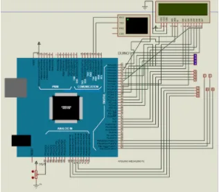
The screenshots show the Proteus circuit, serial interface and LCD. The historical sketch is useful for studying pulse sequencing, but is not a validated controller for a physical arm. Its 12-entry pin array is traversed with a 16-iteration loop, position storage writes signed counts into individual EEPROM bytes, and pulse-derived limits are not independent physical limit sensing. These issues require correction and independent validation before hardware use.
Testing and Real-World Use
This could be tested without hardware by tracing pulse limits, signed position storage and pin-array bounds in the archived sketch. The teach-and-repeat interface illustrates robot command sequencing, but the documented code defects must be corrected and independently validated before any physical use.
Proteus Schematic
Serial Terminal with stored positions
LCD with motor position